|
Efficient heat transfer area: A(㎡)
If more tubes are installed in a regular heat exchanger, it increases heat transfer area.
However, if there is much dead zone, efficient heat transfer area (A) reduces accordingly.
Thus, the point is how to make installed heat area to efficient heat transfer area.
Formula of exchange (recovery) heat rate
Q=AU△Tm
- Q: Exchange(recovery)heat rate(㎉/h)
- A: Efficient heat transfer area (㎡)
- U: Total heat transfer efficiency (㎉/㎡ h°c )
- △Tm: Efficient average temperature difference(°c )
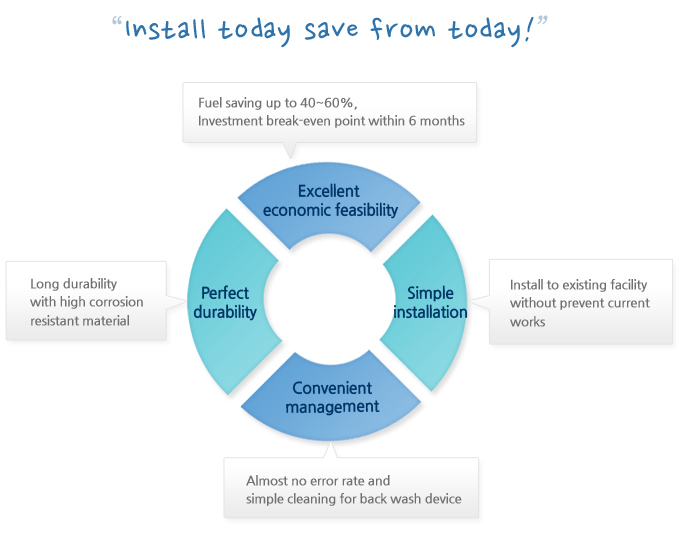
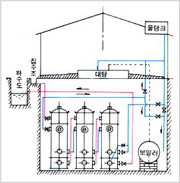
Structure of natural circulation waste heat recovery facility
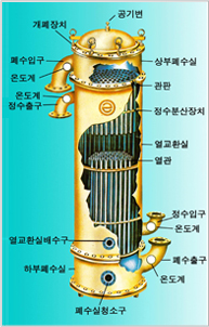
Efficient heat transfer area comparison diagram
The fluid flows toward lowest pressure and nearest area which causes the below phenomenon.
- Primitive form(no baffle plate)(Fig. 2) – Much dead zone
- General form (Vacancy type baffle plate)(Figs.3,4) – Reduced dead zone
- Our waste water heat recovery facility(Fig.1)- No dead zone by water purifying spread device (Patent No. 14894) which makes countercurrent and maximizes efficient heat transfer area with excellent efficiency compared with general heat exchangers
< Principle of natural circulation heat exchanger > |
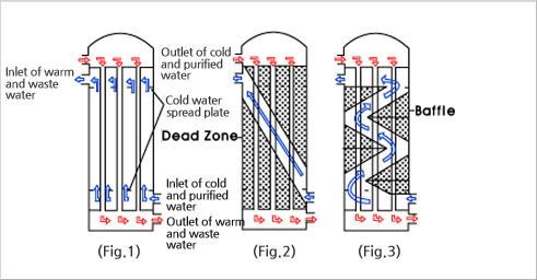
Installation picture |
Installation drawing |
|
|
Use
- It is tailored manufacture by its use
- Main use: Applied to low temperature waste water such as sauna, swimming pool and building
|